Wednesday, February 24, 2016

Web security

People don't understand web security, even many who should

Yesterday I posted a Google+ poll about what is and isn't safe on an unknown Wifi access point, and 93% of the 30 responses were wrong, in spite of the fact that many of the people who follow me are technical and even have a security bent. This did not surprise me.

The question was "You're connected to some random public Wifi hotspot. You know nothing about who owns it or why they make it public (the SSID says it's STARBUCKS and there is a nearby Starbucks, but who knows?), but it gives you a functional Internet connection. Which of the following is safe?"

The three possible answers and their response rates were:
  • Logging onto your bank to transfer money (7%)
  • Reading the news on CNN, or similar (27%)
  • None of the above, unknown Wifi is risky (67%)
The right answer is "Logging onto your bank to transfer money". Congrats to the two voters who got it right.

The fact is that your bank's web site uses TLS to provide an end-to-end secure connection, encrypted and authenticated. There is a possibility that your bank has TLS configured incorrectly, for example by still allowing old versions SSL3 and even SSL2 which have known weaknesses, but it's actually pretty low. Most all banks get this right. If you wonder about yours, there are some free services that check for you. For example, https://www.ssllabs.com/ssltest/.

(Note that the SSLLabs testing protocol is fairly harsh, which is good but perhaps a bit alarmist. If your bank gets a B or a C, scroll down in the report and take a look at the results of simulations with the browser you use. One of the banks I use (Chase) gets a B because it supports use of RC4. Now RC4 isn't actually insecure when used correctly, and TLS does use it correctly, but it's old and no longer recommended. However, my browser (Chrome 47), does not use RC4, so the site/browser combination is green, meaning secure. Some sites also get dinged for not supporting forward secrecy. That's a nice property, but not essential. Don't worry about it.)

So why were the others wrong?

The second option, reading CNN or similar, is wrong because almost no news sites use TLS at all. They're all unencrypted and unauthenticated. This makes them risky all the time, because any attacker anywhere in the chain of routers and servers between you and the origin site can alter the data you receive from them, injecting malware to exploit your browser, tracking cookies (from any origin), drive-by downloads, etc. An attacker can also extract authentication cookies from your browser, for any non-TLS sites you use even without any browser vulnerabilities. But non-TLS sites are particularly risky when you're connected to a random Wifi AP because that is an ideal way for someone to mount these sorts of attacks.

The third option, "just say no", is one I have some sympathy for. And, as the comments on my original post pointed out, it actually may be a correct answer depending on how you interpret "safe". TLS doesn't protect the Wifi operator from seeing what sites you visit, for example, and that list can say a lot about you even if none of your actual information is revealed and even if the data sent to your browser can't be manipulated in dangerous ways. However, if being tracked online is your major concern, you probably just shouldn't use the web at all, unfortunately, so I'm going to discard that definition of "safe". Under a more common interpretation which is that your traffic can't be snooped or your computer (or mobile device) harmed by what you receive, this option is wrong because connecting to your bank, with an up-to-date browser and assuming decent configuration on the bank side, *is* safe, and the "just say no" stance would unnecessarily restrict you.

Others in the comments tried to add additional options to the poll, suggesting that it was safe to use a VPN to a trusted gateway. This is true, but HTTP sites are still inherently less secure than HTTPS sites. Use of the VPN removes the possibly-unscrupulous Wifi operator from the equation, but an attacker who manages to get between the VPN server and CNN can still do anything. Security really needs to be end-to-end.

An interesting point related to VPNs is that Google's security team is eliminating their use for Google employees. Google used to deploy VPN software on almost all portable corporate devices so that employees could securely connect to company systems while traveling, or from home. A couple of years ago they recognized that this was an unnecessary complication and instead they've worked to expose all of the internal systems directly on the Internet, but accessible only via HTTPS (and with tight TLS configurations). Client certificates are issued to corporate devices, and the TLS configuration is set to reject any connection that doesn't have a valid certificate. Actually "exposed" isn't quite the right word, because what's really directly connected to the Internet is a reverse proxy which does the TLS and also implements user authentication (after the connection is established and client cert is verified) using user password and two-factor authentication. The 2FA used in most cases is cryptographic, not a password, from a hardware token (a "security key"). The actual systems receive information from the proxy about what user connected, and don't need to handle any of the TLS or authentication themselves. It's quite elegant, very secure, all standards-based, and doesn't require VPN software, just a modern web browser. Also, _exactly_ the same technology is used for connections coming from inside the corporate network. There's no need to distinguish between "outside" and "inside"; just secure it all.

By the way, I sometimes run into people who don't believe that everything on the web should be encrypted, because lots of stuff just isn't that important. They're wrong. We really need to encrypt and authenticate all Internet traffic.

Thursday, August 27, 2015

Jace's Grade Monitor

My youngest son is a bright kid, but doesn't have much interest in school. He's in 8th grade. It's easy enough for him, but he'd rather play games or watch TV. That has caused him to struggle in school, and resulted in lots of tear-filled evenings when he gets to do nothing but homework because he's behind.

Our solution is to ground him from video games and TV if he's behind in school... and to specify that he isn't allowed to do any of that stuff after school until he's done his homework, but it's pretty hard for us to enforce that, since we don't have up-to-date information on what he's assigned and what he's turned in. We can find out if he's behind or his grades are slipping, though, by looking at the school's on-line gradebook. So, the rule is that if that shows he's behind, or his grades are too low, then he's grounded.

But even that is something of a pain, because it requires us (well, Kristanne) to regularly check the web site, which is often down and almost always slow. And if she's not home when he gets home from school he doesn't know if he's currently behind.

I decided that this problem can be solved with technology. There are several ways I could go about it. I could write a phone app, or put something on the kids' computer. I decided to go with something less subtle: A multi-color LED in the kitchen that shows his current status at all times. If his grades are good, it's green. If they begin to fall, it shades towards yellow and then red. If he's missing assignments, it flashes a count of the missing assignments in blue.

The result is a crude, hack-and-slash assembly of some pretty cool technology. I threw it together in an evening, including learning how to install and configure all the components and write all the code. The components are:
  • A Raspberry Pi 2, (RP2) a small quad-core 700 Mhz ARM computer with 1 GiB of ram and a 32 GiB SD card. It runs Debian Linux.
  • A Spark core, which is an Arduino board with built-in Wifi and an interesting development toolset.
  • A red-green-blue LED.
  • Some resistors to avoid blowing up the LED. I used 330 ohm resistors, which are too big, which means the LED is dimmer than it could be. Oh, well.
My original plan was not to use the Spark, but to wire the LED directly to the GPIO pins on the RP2. But the GPIO headers were male, which means I need a ribbon cable or something else to make it easier to wire them (or I could have soldered wires to them, but that sounded too much like work). So instead I connected the LED to the Spark and I'm using the RP2 to control it.

Here's what the RP2 looks like, in the nifty black case I got for it:


The dongle hanging out the right end is USB Wifi adapter. It's also got an Ethernet jack, if I want to put it where it can be wired.

And here's the LED connected to the Spark core, on a breadboard, with the all-important grade status LED:


For now I just set the whole thing on top of the printer. I'll think about doing something nicer later.

How does it work? The RP2 has a cron job that runs a small script. The script uses curl to download the web page with the grade and assignment information, then pipes it to a Python program that parses the HTML and extracts and summarizes the grade and missing assignment info. The output from the Python program is then used for two more curl invocations, which post the computed values to a server run by Particle.  They make the Spark core.

The Particle server routes the data to the Spark, which is running a trivial Arduino program. Normally you compile Arduino code on your computer and download it to the device via USB. You can do that with the Spark, but for small stuff it's easier to use their web-based tools. They provide a web-based editor into which you type your code, then you click a button and they compile the code to a binary and send it over the Internet to the Spark, which flashes it and reboots.

All very hack and slash... but it works and it was really easy.  The Sparks are pretty cheap, too ($12, IIRC). I have another I'm going to wire into my garage door controller to do some automation on it (because the kids keep leaving the garage open).

Sunday, July 20, 2014

House Site Plan

I don't even want to think about how many hours it took me to put this together.

The county building permit application, the power company service application, the health department application and probably a few others have all required a site plan for my new house. Drawing a simple plan is easy, but the county wants detailed, two-foot contour lines. Obviously, there is no place I can go to get a two-foot contour plot of my property. I contacted a surveyor, but he wanted almost $2K to make me a contour plot.

I figured, how hard can it be?

Well, hard. But it's done. Here's the final version:


To get contour lines, I took a handheld GPS unit with a barometric altimeter and walked the property. And walked, and walked, and walked. As you can see from the final diagram, the land is far from flat. In fact I now know that the total elevation change is 160 feet. But to gather data, I needed to cris-cross the property many, many times, ideally gathering a position and elevation data point every few feet. I walked the whole thing four times, and the last time I walked it I covered six miles and climbed over 2000 feet.

The reason I walked it multiple times was partly because I was learning how to do it, and partly because GPS receivers aren't that accurate. I needed lots of data to help correct for the inaccuracy. GPS is particularly inaccurate when it comes to elevation, but that's why the units I used contain an electronic barometer. The barometer doesn't give them much information about absolute elevation (you can estimate elevation from air pressure, but it's even less precise than GPS elevation), but it provides them fairly precise information about relative elevation. That's what I need. I don't care how far above sea level the property is, I care about how much higher this part is than that part.

GPS receivers also have a fair amount of latitude and longitude error as well. I couldn't find any detailed information about the distribution of the error -- which may actually be different for different devices -- so I assumed it's probably normally distributed and can be reduced by averaging multiple samples together. Because GPS is based on very precise measurements of time signals, if you have multiple GPS receivers you can be guaranteed that they have synchronized time. It may not match up perfectly to wall clock time due to minor adjustments that get made to our clocks, but you can be sure the GPS units all agree.

So, I carried two identical Garmin Rino 130 receivers while I walked. The reason I had two identical ones is because the Rinos are actually walkie-talkies, not just GPS receivers, so it's quite useful to have more than one. But I carried both of them side by side.

After I got back and got the data off them (from all of the multiple runs), I first edited the track logs to remove extraneous data from before and after I started walking. Then I imported the mess into Mathematica. Next, I translated all of the points to try to correct for the fact that every time, every receiver, had the whole property shifted by a few feet in one direction or another. That was actually pretty easy to handle; I took waypoints at each of the corners, on each GPS, during each walk. I picked one of them (the westmost corner) to be my point of reference, and translated each log so that those points matched up.

Actually, I went one further, and translated all of them so that that corner point is (0,0). But more data munging was required. GPS coordinates are recorded as (latitude, longitude), which means they're (y,x), rather than (x,y). So I had to rotate all of the points 90 degrees around my origin to get to (x,y).

Next, I want all the distances on my map to be scaled so that measurements in any direction are valid. That means that one inch on the map should represent a fixed number of feet, no matter whether your ruler is measuring right to left (west to east) or bottom to top (south to north). But latitude and longitude aren't "square" like that in most places. In the area around my property, a millidegree of latitude is approximately 111 meters, and a millidegree of longitude is approximately 84 meters. So the "aspect ratio", the non-squareness, of my coordinate system is about 1.32. So I also scaled all of the y coordinates to "square up" my coordinates. As a result the Euclidean distance between any two points on the map provides a pretty good estimate of the straight-line distance between the real-world points they represent. This sort of scaling to square up only works across relatively small areas, but it's fine for my purposes.

For each walk, I now had two normalized logs, one from each GPSr. I combined them by matching timestamps and averaged the (x,y,z) coordinates from the pair of logs. Mostly. I found a few cases where one of the two devices wandered off and started giving very strange data, so I went back and deleted those points. There was actually a lot of hand-editing of the data to clean up various problems. Here's what I had at this point:


The result is obviously still spotty in some areas, which led to odd-looking contour plots. To fix that, I resampled the entire area at consistent intervals, and for each resampled point I used the mean of the nearest (in (x,y) only) five points. This actually helped with another problem: The fact that the data ends abruptly at the property lines tends to cause the contour plot generation algorithm to do funky things near the edge. My resampling technique resampled the area around the property as well, using the nearest data points. This "extra" data is, of course, complete nonsense, but it's nonsense which is much closer to reality than nothingness, which made the contour plotter happier.

Here's the resampled data, resampled at 200 points on a side, so 40K points total:

There's some waviness towards the center which isn't actually there. I started trying to figure out where it came from and how to smooth it back out, but ultimately decided it didn't matter, because I found that to get nice contour plots I really needed to scale back the level of detail, otherwise the lines were too "jagged". Using a resampling with 30 points on each side, 900 points, here's a contour plot, with the number of contour lines set to provide a vertical distance of two feet per line:


This isn't bad, but the contour lines are still a little too jagged. Applying some rather arbitrary smoothing to the lines, removing the color and cropping to the property lines gives this:

That actually looks really good. I have no doubt that there are some small errors, in fact I can point out some oddities which are almost certainly wrong, but it's the large features match up perfectly.

Good enough. What came next was really time-consuming. I had to add all of the additional details. Among other things, that meant taking the measurements from the house plans and putting them in to create an accurate rendition of the shape of the house, and then placing it in what seems like the right place on the map. Here's the house, already rotated to the right angle for placement on the map. Note that although this image is scale-free, the measurements are actually in my squared-up millidegrees, so when it's superimposed on the contour map, the measurements are all correct.

The enormous gray "turn pad", BTW, is a feature demanded by the fire marshal. I have to provide a hard surface large enough to turn a fire engine around, and that's it. The marshal said I needed 45 feet on a side, that pad is 45x55. I had to lengthen it a bit because of the decorative extension which comes 9 feet off the house. So actual clear turning space is 45x46.

Then I had to add in the well and septic field, barn, driveway, road and all of the "setback" and building size measurements, to produce the final version above.

Mathematica is an awesome tool, and I don't think I could have accomplished this without it. But it was still a lot of work. Okay, so I have thought about how many hours I put in and I'm sure it's around 60. I suppose that's better than spending $2,000. I'll keep telling myself that. Probably 20 of those hours were fun. The rest, not so much.

Wednesday, April 16, 2014

Front Sight Four-day Handgun Course

I got home yesterday from a four-day handgun course at Front Sight in Pahrump, NV (http://frontsight.com). My brief review is: Excellent class, well worth the time, I'd recommend it to anyone who wants to improve their handgun skills.

This is a basic but thorough defensive handgun class. It's basic in that it doesn't try to cover much more than how to draw, shoot, after action and fix malfunctions. It's thorough in that it covers those topics in great depth, teaches you how to build the right muscle memory to do the tactically-correct things under stress and takes you a good way toward actually building that muscle memory, to the degree that most students can draw, aim and fire two aimed shots to center mass of a man-sized silhouette at five meters, all in under 1.5 seconds.

The class is appropriate for everyone from complete novices to experienced handgun shooters. Indeed a friend of mine who is an advanced defensive handgun instructor took it and found it interesting and useful. The class made me a better shooter, and I also picked up a lot of ideas from the way the instructors presented the material and the way they ran the range -- it was very well done and there were a lot of great ideas which will make me a better handgun instructor.

The course covers, safety, presentation, after action, reloading (tactical and emergency) and malfunction clearance (types 1, 2 and 3). It drills the students intensively in those skills, under time pressure to simulate combat stress and develop fluidity and speed. I'll cover each of these briefly, highlighting the areas in which Front Sight's approach differs from others.

Safety. Like any gun school that wants to stay in business Front Sight is very, very careful about safety. The rules are Cooper's normal four rules (I still think rule #1 is pointless and perhaps dangerous, but I didn't argue with them). They do differ by adding some extra and, I think, wise procedures. One important one is the "chamber-check mag-check" process, which they stress is always done as a unit. You never check the chamber without also checking the magazine, even when one or the other is unnecessary, and you always do them the same way and in the same order, because that way you'll never forget one of them when it is necessary. Another is that the "chamber-check mag-check" process must always be performed both before and after changing the state of the gun (loading or unloading), as well as after picking up and before putting a gun down or away.

Presentation. "Presentation" is the fancy (but common, in gun circles) word for drawing the gun from the holster and getting it either into a ready position or in position to shoot. Front Sight teaches a fairly standard five-count presentation. The five counts are:

  1. Acquire a shooting grip on the holstered gun. The support hand goes to the midsection at the same time. If the gun is concealed, the concealment needs to be cleared first. One tidbit I learned: if you're going for speed, focus on moving your support hand faster. It's a simpler motion, easier to speed up, and sympathetic response will move your gun hand faster, too. 
  2. Draw the gun from the holster, moving it straight up to just below the armpit, but leaving it pointed downward. The support hand stays on the midsection. 
  3. Rotate the muzzle up and forward. The support hand stays put. 
  4. Move the support hand to join the shooting hand on the gun. 
  5. Extend the gun outward into position. If moving into firing position, as the gun moves outward the trigger finger moves into the trigger guard and takes up the slack on the trigger. As it rises, the eyes find first the front sight post and then acquires an aligned sight picture. The sights should be aligned and on the target before the gun is fully extended. By the time the gun reaches full extension, all that remains to fire is to finish the trigger press. 
The above is just the bare bones, actually. There are a lot more details involved in making your presentation "perfect", and then a great deal of practice is required to make it smooth, at which point it will also be fast.

Shooting. Front Sight teaches a modified Weaver stance (aka Chapman stance) with the body bladed at 30° from the target, shooting side shoulder back, shooting arm straight, support arm bent. I'm more comfortable with the isoceles stance, so this was difficult for me at first. I could have insisted on my preferred stance, and they'd have been fine with it, but I decided to go along. It worked quite well after I got used to it, but I don't know that I'll stick with it. I need to spend some time experimenting. They also stress follow-through, including trapping the trigger to the rear (continuing the trigger press all the way back, even after the gun has gone off), and reaquiring the sight picture immediately. That's all quite obvious, but I hadn't realized that I have a tendency to skimp on followthrough when I know I'm not going to fire another shot. I'm mostly cured of that, I think.

Like all defensive (and offensive) shooting trainers everywhere, Front Sight teaches shooting to center mass, and specifically to the thoracic cavity (basically everything included inside the rib cage). They also teach shooting "controlled pairs", meaning two shots, followed by a pause to assess. Note that this isn't the same as a double tap, because they teach slowing down between the shots enough to reacquire the sight picture. Under the stress of the brief shoothouse exercise I found I fell back on double tapping. The instructor corrected me.

However, they also teach the "failure to stop" shot, which is a carefully-aimed head shot (specifically to the cranio-ocular cavity, the region between eyebrows and bottom of the nose), to be used when the controlled pair to the thoracic cavity fails to stop, for example if the target is wearing body armor, or is drugged or just sufficiently determined to shrug off the body shots. During shooting drills, the instructor will occasionally yell "Head!", indicating the need for a failure to stop shot. They also teach designated head shots, for cases of hostage situations where the bad guy is mostly shielded behind a hostage.

They are quite clear throughout, though, that the goal of defensive shooting is to stop the attacker, not to kill, and point out that given rapid attention from a fully-equipped trauma center, a person who has received two shots to the thoracic cavity has a roughly 80% chance of survival -- and that's a good thing. I very much approved of the emphasis they put on this, and the way they were quick to step on any talk of shooting to kill. Of course, a head shot is almost invariably fatal, but those are presented as shots of last resort, to be used only when nothing else will do.

After Action. Front Sight teaches a pretty standard after-action process for after the final shot is fired, with lateral movement (to force the opponent to reacquire his sight picture and/or move to cover or concealment), followed by a quick check of the area for additional threats, then a more detailed study of the target to verify that the threat is ended, then a 360° scan to verify the situation really is safe before reholstering the gun. Of course, in the confines of a small range, opportunities for lateral movement are limited to a sidestep to left or right and the 360° scan is limited to a narrow wedge downrange. But within those limitations, the instructors are diligent about ensuring that everyone makes the after action drill a part of every shot sequence, to ingrain it.

They also constantly push to include a tactical reload as the last step of the after action drill. This just means replacing the partially-expended magazine in the gun with a full one, but retaining the partial in a pocket rather than dropping it to the ground. Of course they also teach how to do this smoothly and quickly. I am dramatically faster at loading a new magazine than I was before the class, and can do it in a single motion, from belt to gun, without looking and without lowering the gun from the firing position. And in a fraction of a second. It's a lot easier than I thought... and I already knew it was easy.

(Aside: anyone who thinks that limiting magazine size will significantly impede the ability of active shooters to carry out their rampage should get two minutes of training on how to reload and then spend 15 minutes practicing it.)

Malfunctions. Front Sight teaches and tests (timed!) clearing type 1, 2 and 3 malfunctions, which are failure to fire, failure to eject and failure to feed, respectively. They also incorporate tactical movement into the type 2 and 3 malfunction processes. Into the malfunction training they also add emergency reloads, which is reloading when your gun runs dry and the slide locks back on an empty chamber. This is quite similar to a tactical reload except that the empty magazine is allowed to fall to the ground, and it is not released to drop until the new magazine is already rising to be inserted, so that by the time the opponent has realized you're empty (from the falling magazine), you're no longer empty.

All four days of the course are long and tiring. In the process, you shoot approximately 600 rounds, which means you have to take advantage of any down time to reload magazines. In addition to the range training there are also lectures on firearm selection, combat attitude and mindset, what to do after a gunfight and more. Some of the lectures are sales pitches (SportEar and Legal Shield), but they seem like pretty good products.

The last day includes a fun steel shooting competition among the class members (my class had no winner because both of the finalists shot the hostage), and then the final skills test. The test is fairly difficult. In my class of 40, only eight students passed, plus one who got "distinguished graduate" marks. It requires shooting controlled pairs, under time pressure, from 5, 7, 10 and 15 meters, plus some untimed "failure to stop" head shots at 5 and 7 meters. Then there are a series of timed "designated head shots" at 5 and 7 meters. The times vary depending on distance and type of shot. All are doable, but not in any way generous. The 5 meter controlled pair time is 1.5 seconds, for example, and that includes clearing the cover garment out of the way, drawing, aiming and firing.

I passed, and was one point away from getting distinguished graduate. If any one of three bullets had struck a quarter inch higher on my designated head shots, I'd have made it with points to spare (I lost three points for each of those bullets). My group was tight, about 3/4" across, but low, so it straddled the lower boundary of the line delineating the cranio-ocular cavity. I think I'm yanking the last fraction of an inch on the trigger, pulling the gun down slightly just before it goes off.

Having passed that class, I'm now eligible to take the advanced class, but I think I'd prefer to go to the two-day skill builder class to further tune up my shooting -- and get to the distinguished graduate level. In actual fact, though I think the next class I take will probably be the four-day precision rifle class.

One thing is pretty clear, though, I will be going back. The facility is clean and extremely well-organized, the instructors are friendly, competent and focused on helping students get the most they can out of the class while having a good time and the curriculum is well-designed and well-structured. The days are long and tiring, but fun, and I learned a tremendous amount. I still think the owner, Ignatius Piazza, has a late night infomercial marketing style that is extremely off-putting, and I have serious concerns about whether or not they can continue operating the way they are at the prices I paid, but I have no reservations about the facility, staff or training.

Monday, March 24, 2014

First actual automation project, part 1

I've breadboarded up a few circuits containing various sensors, relays and LEDs, mostly to get some ideas about what I can realistically do with my custom home automation project. As a next step, I decided it would be a good idea to build something simple, and an obvious choice was to continue with an experiment I'd already begun: a "scent lamp".

Kristanne has a small incandescent lamp with a reservoir on top in which she puts scented candle wax. The heat from the bulb melts the wax. This lamp annoys me regularly because she turns it on during the day and then I go to bed, realize the darned thing is still on, and have to get out of bed to go turn it off. For myself, I don't enjoy the scented wax all that much and I'd just as soon get rid of it. But, she likes it, so I want to see if I can automate the thing to make it nicer for both of us.


The Lamp

I've already used this lamp to experiment with controlling a relay, since it was a convenient, low-powered target for my experiment.

What I decided I'd like the lamp to do is to:
  • Turn on during the day and off at night, automatically. This is a backwards from most light controls but it makes sense (and scents, hyuck, hyuck) in this case.
  • Turn on at night when it detects movement. The idea is that when one of us gets up in the middle of the night, the lamp should turn on. It's a small lamp, and not very bright (I believe the bulb is only 30W), so it won't be blinding, but it should provide enough light to be useful.
One potential problem is that we don't want the lamp to turn on randomly all night, for example, when someone rolls over in bed. A little understanding of how PIR motion detectors work and some experimentation provided an easy solution.

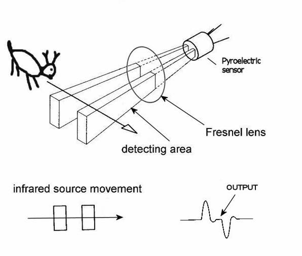
A PIR motion detector consists of a pair of small thermal sensors, adjacent to one another and wired so that the signal that emerges from the pair is the difference between the two. So, as long as both of them are seeing the infrared radiation levels, there's no signal. But when a warm body emitting IR radiation in the right frequency moves in front of them, one sensor will see the heat before the other, which means the difference signal will be non-zero.


However, the two IR sensor windows are thin slits, which means that the sensors have a fairly narrow angle of detection. So, PIR sensors come with a rounded Fresnel lens which bends IR light coming from various angles towards the sensor windows.

The fact that they're two parallel slits also means their ability to detect motion depends on which direction it's moving. If the slits are vertical, positioned side by side, then horizontal movement in front of them will be detected by one before the other, and the movement will register. But a heat source moving vertically into their field of view will be seen by both at once, and no response will be triggered.

So, by removing the Fresnel lens I can narrow the detection field, and by positioning them to observe horizontal, not vertical, movement I can minimize the chance that someone merely rolling over in bed will trigger it. Some experimentation with a sensor pointed at my bed supported this. However, I did notice that the sensor sometimes triggered by movement far off to the side, not directly in front, even without the lens. To fix that, I can set the sensor back into the body of the lamp a bit, so the lamp body blocks IR light from the sides.


The PIR Sensor, with and without lens, and positioned inside the lamp body

One other possible problem became clear in early experimentation: How can a light sensor detect darkness when it's right next to a lamp that's turned on? Without taking some care about positioning, the light from the lamp will cause the sensor to believe it's light, which will keep the light on. All light sensor based lighting controls face this problem, though for most it's inverted.

The answer is to position the sensor so that it receives plenty of ambient light but little from the lamp itself. I decided to put it on top, since the top of the lamp is a solid metal piece. I was a little concerned that the heat might be problematic, but the data sheet for the light sensor says it can operate well above any temperatures the lamp will achieve.

Here's the schematic:


And, while playing with Fritzing, I also created a printed circuit board schematic, designed for an Arduino Mini. I tried hard to arrange things so it would only need a single trace layer, but the trace between R2 (the photocell) and R3 had to cross the 5V line to the PIR so it's in the bottom layer (which is why it's a different color). Also, I jammed things a little tighter than they should normally fit, for example the PIR header block overlaps with the relay and the photocell overlaps both the relay and R3. But that's okay because the photocell and PIR wouldn't actually be mounted on the board. Anyway, here it is:


For $10 I can get that board made by Fritzing Fab. I think I may order it just to experiment with the process and see if I might want to make some custom boards for other things.

I assembled the circuit on Saturday night, with the relay mounted in the base, the PIR in the side and the photocell on top, but the relay didn't work. I think I wired the transistor backwards. I didn't have time to debug and fix it, though, since I work in my bedroom and Kristanne wanted to go to sleep. I guess I need to set up another work area, probably in the basement.

Even if I'd gotten it working, though, it wouldn't have been done, because I was still using the full-sized Arduino Uno board. I ordered a couple of Minis from Sparkfun, to build it for real. The Mini will fit inside the lamp cylinder, opposite the PIR.

After I get it debugged, connected to the Mini and all installed in the lamp, there will still be one piece missing: Power. I need a transformer/rectifier to convert 110 VAC to 5 VDC. I found some circuit diagrams for one of those online, but I think I'll take the easy way out and just hack up a cheap wall USB charger.

All in all, the end result will include some $20 of hardware plus several hours of my time, all to automate a $5 lamp. However, I've learned a lot.

Finally, here's the code. Very simple Arduino code of this sort is normally all in one file, but I separated it to make it easier to write unit tests (which I haven't yet written, but will, and will post in part 2). Here's the untested code.

scent_lamp.h
const int relayPin = 12;
const int motionPin = 13;
const int lightPin = A0;

// Tunable threshold parameters to divide light levels into three categories:
//
// 1. Dark, or night mode. Low enough light that the lamp should be off, except
//    for a little while after detecting motion.
//
// 2. Moderate, or hysteresis mode. The lamp should stay in the state it's
//    already in. This is mainly to prevent flickering rapidly on and off if
//    the light level is right around the dark/light dividing line.
//
// 3. Light, or day mode. High enough light that the lamp should be on.
const int darknessThreshold = 200;
const int lightThreshold = 300;

// Tunable parameter to set the duration the lamp should stay on after
// detecting motion at night, in milliseconds
const unsigned long motionExpirationTimeMillis = 60000L;

bool lampOn;
unsigned long motionExpirationMillis;

bool lampOnPerLightMeasurement(bool currentState);
bool lampOnPerMotionMeasurement();
scent_lamp.ino
#include "scent_lamp.h"

void setup() {
  pinMode(relayPin, OUTPUT);
  pinMode(motionPin, INPUT);
  pinMode(lightPin, INPUT);
  lampOn = true;
  motionExpirationMillis = millis() + motionExpirationTimeMillis;
}

void loop() {
  lampOn = lampOnPerLightMeasurement(lampOn) || lampOnPerMotionMeasurement();
  digitalWrite(relayPin, lampOn ? HIGH : LOW);
}

bool lampOnPerLightMeasurement(bool currentState) {
  int lightDetected = analogRead(lightPin);
  if (lightDetected > lightThreshold) {
    return true;
  } else if (lightDetected < darkThreshold) {
    return false;
  } else {
    return currentState;
  }
}

bool lampOnPerMotionMeasurement() {
  unsigned long now = millis();
  if (digitalRead(motionPin) == HIGH) {
    motionExpirationMillis = now + motionExpirationTimeMillis;
  }
  return motionExpirationMillis > now;
}

Friday, March 21, 2014

Lighting controls for my bathroom

This is actually my second attempt at an Arduino-controlled lighting control circuit, but the first one included only a photoresistive sensor. This one included a magnetic door closure switch, a PIR motion sensor and a phototransistor. It was actually really easy and worked well, except that I think the PIR I bought may not work, since I could never get it to register any motion at all.

I'll detail the wiring and components below, but first I'll explain what I hope to accomplish with something like this. I'm focused first on designing a self-contained lighting control system for my master bathroom. To do it, I need circuitry that can let my software:

  • Tell how much light is present. There's no need to turn on the light if there's enough daylight present. This is for general bathroom lighting; it may make sense to turn additional lights on over the sink for putting on makeup, for example, but I'm assuming that sort of thing will be manual.
  • Tell if the "door" is closed. This is both to help with determining if someone is present and to decide when to turn the light on at night.
  • Tell if someone is moving in view of the PIR (assuming the PIR works), to help determine if someone is present.
  • Turn the light on and off.
One unusual thing about my code for this is that it assumes the light should only turn on when the bathroom door is closed. This is so that I can enter and exit the bathroom without disturbing Kristanne (and vice versa). Opening the door instantly turns off the light. This is also nice because when the door is closed the code can assume that if the PIR has seen motion the bathroom will continue being occupied until the door is opened -- no chance of the light automatically shutting off if you're motionless for several minutes.

This all worked great (except that I had to simulate the PIR, since it wasn't working).

One other tweak I threw in was to change the behavior when the light sensor detected intermediate light levels. If the bathroom is pitch black, that means it's night time and turning on the lights when the door is open is a bad idea. If the bathroom is very light, there's no need to turn them on at all. In between, it may make sense to turn them on, but there's no need to worry about blasting someone in the bedroom with light because it won't increase the brightness that much. Actually, the ideal way to evaluate that is with an additional light sensor in the bedroom -- which I plan to have, though it will probably be connected to the Arduino in that room, so the central automation controller will have to route that signal.

I altered the logic to include handling of this intermediate light state and it worked very nicely in my testing.

BTW, the idea of routing the light status from the bedroom sensor through the central controller to the bathroom controller is a good example of one thing I want to be careful to achieve: I'm fine with some degraded functionality if the individual room controllers are operating independently, but I think they should have enough local intelligence to operate reasonably well. For example, fairly simple light control logic should work, including honoring light on/off requests from the light switches. Inter-room cooperation is nice, but I don't want to have to cross-connect the rooms directly, so all of that will go through the central controller, which will also enable much more intelligent control, including remote control through web and mobile apps, etc.

Anyway, here are the details:

Here's the schematic, without the PIR:

And here's the actual breadboarded circuit (with the PIR):


The relay portion is single-pole, double-throw with 3V coil (needs at least 3V to activate) and can handle up to 10A through the circuit. I used 5V to activate it, with a transistor to switch the coil because the coil draws about 160 mA and the Arduino Uno's data pins can only supply 40 mA. There's also a 220Ω (ish; I think the actual resistor was 270Ω) resistor to limit the current to the transistor base. Pin 12 on the Arduino, configured for OUTPUT, was connected to the resistor and then to the transistor base, so powering that pin switches the relay.

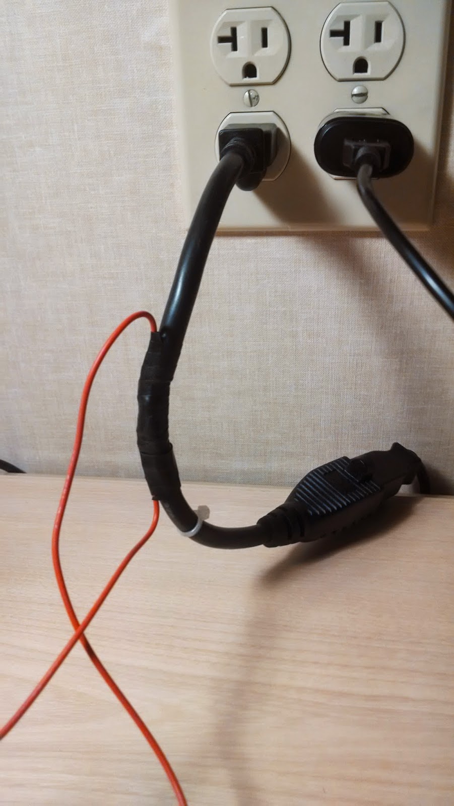
I wired the neutral line of a one-foot extension cord across the normally-open poles of the relay, so activating the relay closes the circuit, then I plugged the extension into the wall and to a desk lamp.


The red wire is 18 AWG solid which, according to the charts I find online, should be good for up to 14A of 120 VAC, so that's safe-ish, though a real circuit should have a 10A fuse. A real circuit should also not leave the relay poles exposed where someone could touch them, and should be soldered or screwed!

The phototransistor's negative side was connected to ground through a resistor, essentially a pull-down, and the positive side connected directly to 5V, and also to the the A0 analog input pin on the Arduino, configured as an INPUT pin. By varying the size of the resistor I could control the amount of light that triggered different input levels on A0. I need to think about what exactly that resistor was doing, electrically -- I'm still not 100% clear on how pulldowns and pullups work.

The magnetic switch is the simplest: One wire is connected to ground and the other to pin 4, configured as INPUT_PULLUP. Putting the magnet by the reed switch (within about 1/2 inch) causes the reed switch to close and the pin to read LOW. Moving it away opens the switch and causes the pin to read HIGH.

The PIR sensor circuit is also trivial to wire: three pins one goes to +5V, one to ground and the last is a data pin which should go HIGH whenever the device sees movement. There is a calibration needed at power up, but that basically consists of waiting 30 seconds before trying to read it. But my data pin never went HIGH. Dunno.

I'll add the code later, since I want to clean it up a little before posting it.

Sunday, March 16, 2014

Presence detection: ultrasonic ranging.

Since several aspects of effective automation (at least the sort I want) depend on being able to tell where people are at, I decided last week to start experimenting with sensors.

I know that the primary sensor throughout the house will be PIR motion sensors. They're cheap and effective, but generally only tell you "a heat source moved somewhere in my field of view". I want to get more information about comings and goings, with an eye to being able to accurately track numbers of people in each room.

One of the ideas I has was to use ultrasonic rangefinders mounted so they're aimed at doorways, hallways and other natural chokepoints, positioned so that people will be walking directly toward or away from the rangefinder. The idea is that when no people are present it will always see the range to the far wall or whatever. When people are moving through the chokepoint, the range will be to the person, and by taking repeated samples we can see if the person is moving toward the sensor or away from it.

I also thought it might be a good idea to place these on the ceiling, angled down, to increase the chance that if multiple people walk through it sees all of them, rather than just the first. That was the idea, anyway.

So, I bought one of these:
The first lesson I learned was to do price comparisons. I paid $10 for mine, but after I got it found other places selling it for $2.99. Oh, well. This SR-04 unit is fairly short-ranged, only out to about 15 feet, but I thought that would be just fine particularly if it were ceiling-mounted and looking slightly downward.

Anyway, I poked it into the breadboard, looked up the datasheet to see how to use it and gave it a try. Using it is pretty simple. As the labels imply, pin 1 is power (+5V) and pin 4 is ground. Pin 2 is "trigger" and 3 is "echo". What that means is that if you pull pin 2 high (+5V) for at least 2 microseconds, then pull it back to zero, you'll have "triggered" the device. It will then pull pin 3 high, send a series of very brief ultrasonic audio pulses and then pull pin 3 low when the echo of the last arrives. You have to wait at least 50 ms before triggering again.

With respect to wiring, it's really that simple. No need for extra resistors or anything; just connect the power, the ground, one output pin and one input pin and you're good.

The software is a little more complicated, though also not bad. First, as soon as you pull pin 2 back low, you need to start a timer, counting microseconds. Then as soon as pin 3 goes low, stop the timer. That timer will give you the time in microseconds that the sound took to get from the emitter and back to the microphone. The Arduino library function pulseIn will actually do all of the timing and monitoring of the input pin for you.

Once you have the echo duration, there's a little more work to do because you have to convert that to distance. Sound travels at approximately 1130 feet per second at standard temperature and pressure, which is 13,560 inches per second. Taking the reciprocal give us ~.000074 seconds per inch, which is 74 microseconds. So, we just have to take the echo time (which is in microseconds) and divide by 74, right? Almost, that echo time is the round trip time, out and back. For a one-way distance measure, we need to divide by two.

So the code is something like:

void setup() {
  pinMode(echoPin, INPUT);
  pinMode(triggerPin, OUTPUT);
}

void loop() {
  digitalWrite(triggerPin, LOW);
  delayMicroseconds(2);
  digitalWrite(triggerPin, HIGH);
  delayMicroseconds(10); // Must be at least 2μs
  digitalWrite(triggerPin, LOW);

  long duration = pulseIn(echoPin, HIGH);
  int distanceInches = (int)(duration / 74 / 2);

  // Do something with distance here.

  delay(50); // Wait 50 ms before polling again.
}

Of course, real code will be more complex, but that covers the basics of using the sensor.

So how awesome was it? Not very. I've since found a library, called newPing that purports to do a better job of extracting data from the sensor by using lower-level primitives to do the timing rather than calling pulseIn, but I suspect it still won't be very good.

When I first started playing with it, I noticed that it often returned a nonsensically-huge value. I quickly realized that that was the sensor's way of saying "I never got the echo". That was fine; I knew it had a limited range and the other side of my bedroom was farther than 15 feet. When I put my hand very near the sensor (2-8 inches), the sensor was reliable and accurate, but as I moved farther back I started getting the out-of-range value mixed in with sensible values. The farther back I moved the worse it got, to the point that more than about three feet away it hardly saw me at all.

I started thinking about what an ultrasonic ranger does and realized that my soft body and clothing is not a very reflective target. I'm rounded, which means large portions of my body are not perpendicular to the incoming sound wave and will therefore get reflected off in all sorts of directions.

So, I went and got a large hardcover book and held that in front of the sensor... it was flawless right out to the maximum range of the sensor, and a bit beyond. But the book was a nearly ideal surface, hard and flat. At least it was perfect as long as I held it perpendicular to the line between the sensor and book. If I angled it off to the side the sensor immediately started reporting max values again.

The angle issue points out that mounting them in the ceiling looking downward would likely not work, even if people were more reflective, because the sound will bounce off at an angle, heading to the floor rather than back to the sensor. If the microphone were in the floor... but that's not feasible.

I tried various simple filters, first ignoring out-of-range values, then taking a mean, or a median, of multiple samples, and while the filtering helped a little, it still didn't work well. Human bodies just aren't good targets for simple ultrasonic ranging.

I'll experiment a bit more with newPing, just to see if it makes a difference, but I think ultrasonics probably aren't the best choice for this application.

My collection is complete(ish)!

I drive an electric car, a Tesla Model S. Generally, I never worry about how or where to charge it. It has a large battery and a long range,...