Monday, March 24, 2014

First actual automation project, part 1

I've breadboarded up a few circuits containing various sensors, relays and LEDs, mostly to get some ideas about what I can realistically do with my custom home automation project. As a next step, I decided it would be a good idea to build something simple, and an obvious choice was to continue with an experiment I'd already begun: a "scent lamp".

Kristanne has a small incandescent lamp with a reservoir on top in which she puts scented candle wax. The heat from the bulb melts the wax. This lamp annoys me regularly because she turns it on during the day and then I go to bed, realize the darned thing is still on, and have to get out of bed to go turn it off. For myself, I don't enjoy the scented wax all that much and I'd just as soon get rid of it. But, she likes it, so I want to see if I can automate the thing to make it nicer for both of us.


The Lamp

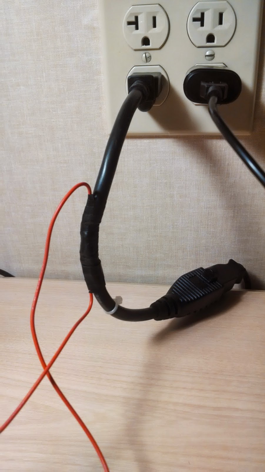
I've already used this lamp to experiment with controlling a relay, since it was a convenient, low-powered target for my experiment.

What I decided I'd like the lamp to do is to:
  • Turn on during the day and off at night, automatically. This is a backwards from most light controls but it makes sense (and scents, hyuck, hyuck) in this case.
  • Turn on at night when it detects movement. The idea is that when one of us gets up in the middle of the night, the lamp should turn on. It's a small lamp, and not very bright (I believe the bulb is only 30W), so it won't be blinding, but it should provide enough light to be useful.
One potential problem is that we don't want the lamp to turn on randomly all night, for example, when someone rolls over in bed. A little understanding of how PIR motion detectors work and some experimentation provided an easy solution.

A PIR motion detector consists of a pair of small thermal sensors, adjacent to one another and wired so that the signal that emerges from the pair is the difference between the two. So, as long as both of them are seeing the infrared radiation levels, there's no signal. But when a warm body emitting IR radiation in the right frequency moves in front of them, one sensor will see the heat before the other, which means the difference signal will be non-zero.


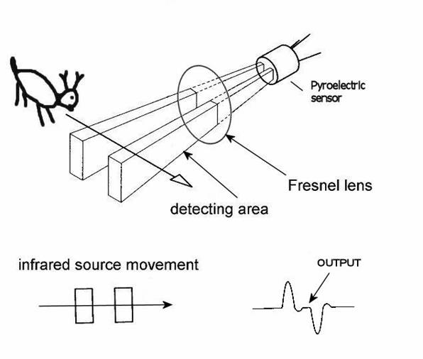
However, the two IR sensor windows are thin slits, which means that the sensors have a fairly narrow angle of detection. So, PIR sensors come with a rounded Fresnel lens which bends IR light coming from various angles towards the sensor windows.

The fact that they're two parallel slits also means their ability to detect motion depends on which direction it's moving. If the slits are vertical, positioned side by side, then horizontal movement in front of them will be detected by one before the other, and the movement will register. But a heat source moving vertically into their field of view will be seen by both at once, and no response will be triggered.

So, by removing the Fresnel lens I can narrow the detection field, and by positioning them to observe horizontal, not vertical, movement I can minimize the chance that someone merely rolling over in bed will trigger it. Some experimentation with a sensor pointed at my bed supported this. However, I did notice that the sensor sometimes triggered by movement far off to the side, not directly in front, even without the lens. To fix that, I can set the sensor back into the body of the lamp a bit, so the lamp body blocks IR light from the sides.


The PIR Sensor, with and without lens, and positioned inside the lamp body

One other possible problem became clear in early experimentation: How can a light sensor detect darkness when it's right next to a lamp that's turned on? Without taking some care about positioning, the light from the lamp will cause the sensor to believe it's light, which will keep the light on. All light sensor based lighting controls face this problem, though for most it's inverted.

The answer is to position the sensor so that it receives plenty of ambient light but little from the lamp itself. I decided to put it on top, since the top of the lamp is a solid metal piece. I was a little concerned that the heat might be problematic, but the data sheet for the light sensor says it can operate well above any temperatures the lamp will achieve.

Here's the schematic:


And, while playing with Fritzing, I also created a printed circuit board schematic, designed for an Arduino Mini. I tried hard to arrange things so it would only need a single trace layer, but the trace between R2 (the photocell) and R3 had to cross the 5V line to the PIR so it's in the bottom layer (which is why it's a different color). Also, I jammed things a little tighter than they should normally fit, for example the PIR header block overlaps with the relay and the photocell overlaps both the relay and R3. But that's okay because the photocell and PIR wouldn't actually be mounted on the board. Anyway, here it is:


For $10 I can get that board made by Fritzing Fab. I think I may order it just to experiment with the process and see if I might want to make some custom boards for other things.

I assembled the circuit on Saturday night, with the relay mounted in the base, the PIR in the side and the photocell on top, but the relay didn't work. I think I wired the transistor backwards. I didn't have time to debug and fix it, though, since I work in my bedroom and Kristanne wanted to go to sleep. I guess I need to set up another work area, probably in the basement.

Even if I'd gotten it working, though, it wouldn't have been done, because I was still using the full-sized Arduino Uno board. I ordered a couple of Minis from Sparkfun, to build it for real. The Mini will fit inside the lamp cylinder, opposite the PIR.

After I get it debugged, connected to the Mini and all installed in the lamp, there will still be one piece missing: Power. I need a transformer/rectifier to convert 110 VAC to 5 VDC. I found some circuit diagrams for one of those online, but I think I'll take the easy way out and just hack up a cheap wall USB charger.

All in all, the end result will include some $20 of hardware plus several hours of my time, all to automate a $5 lamp. However, I've learned a lot.

Finally, here's the code. Very simple Arduino code of this sort is normally all in one file, but I separated it to make it easier to write unit tests (which I haven't yet written, but will, and will post in part 2). Here's the untested code.

scent_lamp.h
const int relayPin = 12;
const int motionPin = 13;
const int lightPin = A0;

// Tunable threshold parameters to divide light levels into three categories:
//
// 1. Dark, or night mode. Low enough light that the lamp should be off, except
//    for a little while after detecting motion.
//
// 2. Moderate, or hysteresis mode. The lamp should stay in the state it's
//    already in. This is mainly to prevent flickering rapidly on and off if
//    the light level is right around the dark/light dividing line.
//
// 3. Light, or day mode. High enough light that the lamp should be on.
const int darknessThreshold = 200;
const int lightThreshold = 300;

// Tunable parameter to set the duration the lamp should stay on after
// detecting motion at night, in milliseconds
const unsigned long motionExpirationTimeMillis = 60000L;

bool lampOn;
unsigned long motionExpirationMillis;

bool lampOnPerLightMeasurement(bool currentState);
bool lampOnPerMotionMeasurement();
scent_lamp.ino
#include "scent_lamp.h"

void setup() {
  pinMode(relayPin, OUTPUT);
  pinMode(motionPin, INPUT);
  pinMode(lightPin, INPUT);
  lampOn = true;
  motionExpirationMillis = millis() + motionExpirationTimeMillis;
}

void loop() {
  lampOn = lampOnPerLightMeasurement(lampOn) || lampOnPerMotionMeasurement();
  digitalWrite(relayPin, lampOn ? HIGH : LOW);
}

bool lampOnPerLightMeasurement(bool currentState) {
  int lightDetected = analogRead(lightPin);
  if (lightDetected > lightThreshold) {
    return true;
  } else if (lightDetected < darkThreshold) {
    return false;
  } else {
    return currentState;
  }
}

bool lampOnPerMotionMeasurement() {
  unsigned long now = millis();
  if (digitalRead(motionPin) == HIGH) {
    motionExpirationMillis = now + motionExpirationTimeMillis;
  }
  return motionExpirationMillis > now;
}

Friday, March 21, 2014

Lighting controls for my bathroom

This is actually my second attempt at an Arduino-controlled lighting control circuit, but the first one included only a photoresistive sensor. This one included a magnetic door closure switch, a PIR motion sensor and a phototransistor. It was actually really easy and worked well, except that I think the PIR I bought may not work, since I could never get it to register any motion at all.

I'll detail the wiring and components below, but first I'll explain what I hope to accomplish with something like this. I'm focused first on designing a self-contained lighting control system for my master bathroom. To do it, I need circuitry that can let my software:

  • Tell how much light is present. There's no need to turn on the light if there's enough daylight present. This is for general bathroom lighting; it may make sense to turn additional lights on over the sink for putting on makeup, for example, but I'm assuming that sort of thing will be manual.
  • Tell if the "door" is closed. This is both to help with determining if someone is present and to decide when to turn the light on at night.
  • Tell if someone is moving in view of the PIR (assuming the PIR works), to help determine if someone is present.
  • Turn the light on and off.
One unusual thing about my code for this is that it assumes the light should only turn on when the bathroom door is closed. This is so that I can enter and exit the bathroom without disturbing Kristanne (and vice versa). Opening the door instantly turns off the light. This is also nice because when the door is closed the code can assume that if the PIR has seen motion the bathroom will continue being occupied until the door is opened -- no chance of the light automatically shutting off if you're motionless for several minutes.

This all worked great (except that I had to simulate the PIR, since it wasn't working).

One other tweak I threw in was to change the behavior when the light sensor detected intermediate light levels. If the bathroom is pitch black, that means it's night time and turning on the lights when the door is open is a bad idea. If the bathroom is very light, there's no need to turn them on at all. In between, it may make sense to turn them on, but there's no need to worry about blasting someone in the bedroom with light because it won't increase the brightness that much. Actually, the ideal way to evaluate that is with an additional light sensor in the bedroom -- which I plan to have, though it will probably be connected to the Arduino in that room, so the central automation controller will have to route that signal.

I altered the logic to include handling of this intermediate light state and it worked very nicely in my testing.

BTW, the idea of routing the light status from the bedroom sensor through the central controller to the bathroom controller is a good example of one thing I want to be careful to achieve: I'm fine with some degraded functionality if the individual room controllers are operating independently, but I think they should have enough local intelligence to operate reasonably well. For example, fairly simple light control logic should work, including honoring light on/off requests from the light switches. Inter-room cooperation is nice, but I don't want to have to cross-connect the rooms directly, so all of that will go through the central controller, which will also enable much more intelligent control, including remote control through web and mobile apps, etc.

Anyway, here are the details:

Here's the schematic, without the PIR:

And here's the actual breadboarded circuit (with the PIR):


The relay portion is single-pole, double-throw with 3V coil (needs at least 3V to activate) and can handle up to 10A through the circuit. I used 5V to activate it, with a transistor to switch the coil because the coil draws about 160 mA and the Arduino Uno's data pins can only supply 40 mA. There's also a 220Ω (ish; I think the actual resistor was 270Ω) resistor to limit the current to the transistor base. Pin 12 on the Arduino, configured for OUTPUT, was connected to the resistor and then to the transistor base, so powering that pin switches the relay.

I wired the neutral line of a one-foot extension cord across the normally-open poles of the relay, so activating the relay closes the circuit, then I plugged the extension into the wall and to a desk lamp.


The red wire is 18 AWG solid which, according to the charts I find online, should be good for up to 14A of 120 VAC, so that's safe-ish, though a real circuit should have a 10A fuse. A real circuit should also not leave the relay poles exposed where someone could touch them, and should be soldered or screwed!

The phototransistor's negative side was connected to ground through a resistor, essentially a pull-down, and the positive side connected directly to 5V, and also to the the A0 analog input pin on the Arduino, configured as an INPUT pin. By varying the size of the resistor I could control the amount of light that triggered different input levels on A0. I need to think about what exactly that resistor was doing, electrically -- I'm still not 100% clear on how pulldowns and pullups work.

The magnetic switch is the simplest: One wire is connected to ground and the other to pin 4, configured as INPUT_PULLUP. Putting the magnet by the reed switch (within about 1/2 inch) causes the reed switch to close and the pin to read LOW. Moving it away opens the switch and causes the pin to read HIGH.

The PIR sensor circuit is also trivial to wire: three pins one goes to +5V, one to ground and the last is a data pin which should go HIGH whenever the device sees movement. There is a calibration needed at power up, but that basically consists of waiting 30 seconds before trying to read it. But my data pin never went HIGH. Dunno.

I'll add the code later, since I want to clean it up a little before posting it.

Sunday, March 16, 2014

Presence detection: ultrasonic ranging.

Since several aspects of effective automation (at least the sort I want) depend on being able to tell where people are at, I decided last week to start experimenting with sensors.

I know that the primary sensor throughout the house will be PIR motion sensors. They're cheap and effective, but generally only tell you "a heat source moved somewhere in my field of view". I want to get more information about comings and goings, with an eye to being able to accurately track numbers of people in each room.

One of the ideas I has was to use ultrasonic rangefinders mounted so they're aimed at doorways, hallways and other natural chokepoints, positioned so that people will be walking directly toward or away from the rangefinder. The idea is that when no people are present it will always see the range to the far wall or whatever. When people are moving through the chokepoint, the range will be to the person, and by taking repeated samples we can see if the person is moving toward the sensor or away from it.

I also thought it might be a good idea to place these on the ceiling, angled down, to increase the chance that if multiple people walk through it sees all of them, rather than just the first. That was the idea, anyway.

So, I bought one of these:
The first lesson I learned was to do price comparisons. I paid $10 for mine, but after I got it found other places selling it for $2.99. Oh, well. This SR-04 unit is fairly short-ranged, only out to about 15 feet, but I thought that would be just fine particularly if it were ceiling-mounted and looking slightly downward.

Anyway, I poked it into the breadboard, looked up the datasheet to see how to use it and gave it a try. Using it is pretty simple. As the labels imply, pin 1 is power (+5V) and pin 4 is ground. Pin 2 is "trigger" and 3 is "echo". What that means is that if you pull pin 2 high (+5V) for at least 2 microseconds, then pull it back to zero, you'll have "triggered" the device. It will then pull pin 3 high, send a series of very brief ultrasonic audio pulses and then pull pin 3 low when the echo of the last arrives. You have to wait at least 50 ms before triggering again.

With respect to wiring, it's really that simple. No need for extra resistors or anything; just connect the power, the ground, one output pin and one input pin and you're good.

The software is a little more complicated, though also not bad. First, as soon as you pull pin 2 back low, you need to start a timer, counting microseconds. Then as soon as pin 3 goes low, stop the timer. That timer will give you the time in microseconds that the sound took to get from the emitter and back to the microphone. The Arduino library function pulseIn will actually do all of the timing and monitoring of the input pin for you.

Once you have the echo duration, there's a little more work to do because you have to convert that to distance. Sound travels at approximately 1130 feet per second at standard temperature and pressure, which is 13,560 inches per second. Taking the reciprocal give us ~.000074 seconds per inch, which is 74 microseconds. So, we just have to take the echo time (which is in microseconds) and divide by 74, right? Almost, that echo time is the round trip time, out and back. For a one-way distance measure, we need to divide by two.

So the code is something like:

void setup() {
  pinMode(echoPin, INPUT);
  pinMode(triggerPin, OUTPUT);
}

void loop() {
  digitalWrite(triggerPin, LOW);
  delayMicroseconds(2);
  digitalWrite(triggerPin, HIGH);
  delayMicroseconds(10); // Must be at least 2μs
  digitalWrite(triggerPin, LOW);

  long duration = pulseIn(echoPin, HIGH);
  int distanceInches = (int)(duration / 74 / 2);

  // Do something with distance here.

  delay(50); // Wait 50 ms before polling again.
}

Of course, real code will be more complex, but that covers the basics of using the sensor.

So how awesome was it? Not very. I've since found a library, called newPing that purports to do a better job of extracting data from the sensor by using lower-level primitives to do the timing rather than calling pulseIn, but I suspect it still won't be very good.

When I first started playing with it, I noticed that it often returned a nonsensically-huge value. I quickly realized that that was the sensor's way of saying "I never got the echo". That was fine; I knew it had a limited range and the other side of my bedroom was farther than 15 feet. When I put my hand very near the sensor (2-8 inches), the sensor was reliable and accurate, but as I moved farther back I started getting the out-of-range value mixed in with sensible values. The farther back I moved the worse it got, to the point that more than about three feet away it hardly saw me at all.

I started thinking about what an ultrasonic ranger does and realized that my soft body and clothing is not a very reflective target. I'm rounded, which means large portions of my body are not perpendicular to the incoming sound wave and will therefore get reflected off in all sorts of directions.

So, I went and got a large hardcover book and held that in front of the sensor... it was flawless right out to the maximum range of the sensor, and a bit beyond. But the book was a nearly ideal surface, hard and flat. At least it was perfect as long as I held it perpendicular to the line between the sensor and book. If I angled it off to the side the sensor immediately started reporting max values again.

The angle issue points out that mounting them in the ceiling looking downward would likely not work, even if people were more reflective, because the sound will bounce off at an angle, heading to the floor rather than back to the sensor. If the microphone were in the floor... but that's not feasible.

I tried various simple filters, first ignoring out-of-range values, then taking a mean, or a median, of multiple samples, and while the filtering helped a little, it still didn't work well. Human bodies just aren't good targets for simple ultrasonic ranging.

I'll experiment a bit more with newPing, just to see if it makes a difference, but I think ultrasonics probably aren't the best choice for this application.

House: Automation Overview

There will undoubtedly be a large volume of posts about automation, as I figure out various sensors, filtering algorithms, control systems, etc., but I'll start with an overview of the ideas I'm playing with.

When in Doubt, Connect It

To begin with, my default assumption is that it's better to connect everything, even if I can't think of a reason to connect it right now. That means embed every possible sensor and enable control of every possible device -- or, at a minimum, ensure that the wiring is in place to make it possible to connect everything later if it's too expensive or time-consuming to do it up front.

Sensor examples:
  • Closure sensors on every door and window, inside and outside.
  • Temperature, humidity and light sensors in every room, perhaps multiple places in each room.
  • Microphone(s) in every room (I need to think hard about the privacy aspects there; but part of the idea is to enable a nice custom-designed intercom system).
  • Camera(s) in "public" rooms and outside.
  • Weather station outside -- temperature, humidity, barometric pressure, rain gauge, wind speed and direction, etc.
  • "Presence sensors" in every room. I use scare quotes because I haven't yet decided what kinds of actual sensors make the most sense, I'm playing with infrared motion sensors, microwave doppler radar motion sensors, ultrasonic ranging sensors and photoelectric sensors... and that's just what I've found so far. The goal is to know if people are in each room and, ideally, how many. If possible, it'd be really awesome to know who, but that seems more difficult without making people carry some device (like, maybe, a cellphone).
  • Flow meters on water lines.
  • Flow meters and temperature sensors on radiant heat loops.
  • Current sensors on electrical circuits.
  • Light switches.
Examples things to control:
  • Heating / cooling system
  • Windows
  • Blinds
  • Lights
  • Outlets
  • Water valves
  • Ceiling-mounted speaker system
Further, on the control aspect, every device should be individually controllable. I can't imagine why, for example, I'd want to send an audio signal to the ceiling speaker in one corner of a room and a different signal to the speaker in another corner of the room, but it should be possible. Actually, I can think of several reasons now that I consider it.

Data Wiring Strategy

I first started thinking that I wanted to run control and sensor lines from every device to one central location, the basement utility room. As my ideas about what I want to control/measure have expanded, though, I've realized that's just too much. It would be a huge bundle of wires, especially since I'm planning to use cat 5 everywhere, on the theory that it's cheap and it provides eight 24 AWG strands, four twisted pairs, to each location.


I don't think anything I have planned will benefit from the interference reduction provided by the twisting, but the stuff is cheap.

So, instead I think I'm going to do the wiring on a per-room basis. I'll run all of the wires for a given room to a single location (perhaps two locations for big rooms) and put a multi-gang light switch box there — that's the sort of box which holds multiple light switches together. Light switch boxes are common (and therefore cheap) and you can also get cheap and attractive blank face plates for them. Using large ones should provide plenty of room.

At each such concentration point I'll use a microcontroller (probably just a standard Arduino board with a shift register shield) to collect all the signals and to send all the control messages. Speaker wiring will have to be separate, of course, but it will go to the same point, perhaps to a separate box.

From each concentration point I'll run four cat-5 lines down to the utility room in the basement. One should be enough to provide power and connectivity to the control board, but redundancy is good.

In the utility room I'll put the central control system. It will need to be a beefier, more capable device than is easily achievable with Arduino-style microcontrollers, so I'm leaning towards a Raspberry Pi. That seems like the ideal device for a controller -- low power and simple enough to be highly reliable, with no moving parts (fans, spinning disks, etc.), but a real Linux system with Ethernet for network connectivity and a moderately powerful CPU.

Automation Ideas

So that's the infrastructure. What to do with it? Here are a few ideas I have now; more will undoubtedly come to me.

Lights

The goal is never to have to touch a light switch. There should be light switches in case there's a need to override the automation system's decisions, but most of the time the lights should come on ahead of you and turn off behind you completely automatically as you walk around the house — and obviously they should only turn on when it's dark enough to require them.

The key to making this work is presence detection. The system needs to be able to figure out where people are and where they are not, and to do so reliably. Passive infrared (PIR) motion detectors are used for lots of systems like this, but the common approach just turns on the light when a moving heat source (a person) is detected and then turn it off after some adjustable period of time. That's simple, but leads to lights turning off when people are stationary, and to lights being left on unnecessarily for the timer duration when people have left.

Another idea I'm toying with is having the system automatically use lower lighting levels after bedtime. So if you get up and walk around in the middle of the night, lights will still come on but they'll be fewer, or dimmer, so as not to be blinding. It should also be trivial to make lights come on automatically in the morning, as part of an alarm system.

Climate Control

It's already very easy and cheap to get a Wifi-enabled thermostat that provides sophisticated temperature scheduling and remote control. What I want to do is to go a step further and automate use of exterior weather changes to make the system more efficient and more accurate.

The biggest component of that is windows. Windows should be open whenever the outside temperature is closer to the goal than the inside temperature, and whenever other ambient conditions don't indicate that opening windows is a bad idea, for example if it's raining or windy. Another element is blinds, especially for the great room. During hot summer days, when the sun is at an angle that puts a lot of light and heat into the room, we want to lower the shades to block that. For that matter, if the sun ever reaches an angle that makes sitting in the room unpleasant, the shades should be lowered to block that as well. (Note that interior vs exterior shades is an open question: Exterior shades are much more effective at blocking heat, but are more expensive and require more maintenance. Interior shades have to let the light into the room then reflect it out, so aren't as effective. But if they're white they should still be pretty good.)

Sound System & Intercom

I'd like to see if I can make music, or other audio (audiobooks, actually), follow me around the house. Rather than sending the same signal to the entire house, which is both wasteful and potentially annoying to people, if I can devise a way for the house to know where I (and others) are at, and arrange to direct the audio appropriately, a given person's music, book, radio station, etc., can play in whatever room they're in.

The two key technology problems to solve are (1) locating people and (2) routing audio. For (1), I'm thinking iBeacons in each room with Bluetooth Low Energy-equipped smartphones detecting the nearest beacon and informing the system. This means the audio will actually follow the phones, not the people, but that seems acceptable.

Related, I'd like to build a smart intercom system that can address either specific rooms or specific people (if they happen to have a phone so their location is known). Using a small control panel in each room (probably mounted into the face plate covering the room's control box), it should be possible to select a room or a person and then use the microphones and speakers in both rooms. Alternatively (or in addition) a smartphone app can be used to establish one end of the connection with the room microphone and speakers as the other. Of course... if both parties have phones, you could also just make a phone call, but that's no fun.

I'm also interested in seeing if I can build a whole-house, always-listening interface to Google Now, or similar. I love how I can say "OK Google Now" any time my phone is nearby and then give it commands, ask it to search for things, etc. Something like that which works any time, anywhere in the house would be awesome.

Water and Energy Efficiency

Measuring water and electricity usage in detail should provide a lot of information that can be used to help optimize the system. Given that we'll be getting water from a well, not paying for metered usage, water efficiency may seem to be unimportant but I'd still like to see what's going on.

Hall-effect flow meters on the Pex lines coming out of the water manifold will provide good water usage measurement, and on a per-faucet basis. CT sensors on the lines out of the main electrical box will provide fairly detailed energy measurement.

Water valves could be added at the manifold to automatically turn water on and off, too. The only application I've come up with so far for that, though, is to turn off the hot water if my kids are showering for too long :-)

If you don't know what I mean by "water manifold", it's one of these. This new style of residential plumbing uses a home-run or star topology. Every faucet in the house has a line running directly to the utility room.


Door and Window Closure

For exterior doors and windows, the system can monitor closure state, to let me know, for example, if everything is locked up when I'm away, or at night. Another clever idea given to me by Charles Hardy is to mount sensors in the deadbolt receivers, so the system knows when the deadbolts are engaged. I spent some time looking for switches that would work without finding anything, but then I hit on the idea of just putting a pair of small springs in each receiver, arranged so the springs cannot touch one another, but will both touch the deadbolt when engaged. That will create a nice switch that closes when the bolt is thrown

For interior closure sensors I don't want to use the big, blocky devices normally used for security systems, but I found there are some small, inexpensive devices that are designed to be embedded in door frames.


These are 3/8" in diameter, so you just need to drill a small hole in the door frame to hold the sensor (a reed switch) and wire that up, and another small hole in the door into which you glue the magnet. When the two come within 3/4" of one another the switch will close indicating door closure. They cost about $2 each.


Saturday, March 15, 2014

Heating and Cooling

Heating

I think we're going to use a hydronic underfloor radiant heat system. Underfloor radiant heat is supposed to be considerably more efficient than forced air, because it provides better heat distribution. As the image shows, forced air heats rooms unevenly, and the hot air tends to accumulate at the ceilings, particularly in homes with high ceilings. I'm not sure the image is completely accurate; other resources I find on the web indicate that heat still accumulates near the ceiling, which makes a lot more sense thermodynamically than what the image shows.

However, radiant floor systems do produce a much smaller difference in heat between ceiling and floor. While forced air systems often have 15+-degree differences between the cool floor areas away from heat registers and high points in ceilings, radiant systems generally see no more than 2-4 degrees difference. This makes radiant heat systems more efficient, since you're not overheating one area in order to achieve a comfortable temperature elsewhere.

They're also, by all accounts, simply more comfortable. Since the heat comes from below, radiant head means that your feet will be warm. I tend to have problems with perpetually-cold feet, so that sounds really nice to me. Plus, imagine never stepping onto a cold floor in winter time!

Cooling

For cooling, hydronic floor systems are also useful, but only to a limited degree. Cooling the floors below about 68 degrees is said to cause in-floor condensation, which is bad. I'm not sure that is as great a problem in Utah, given how dry the Rocky Mountain air is, but it's probably a good guideline. Still, hydronic radiant systems can do a great deal to cool a home as long as the air temperatures don't get too high. Given that Morgan isn't that hot in the summer, and given that the air cools down significantly at night, I think we may actually be able to avoid using air conditioning most, if not all, of the time.

A key component of making summer cooling work well is another high-tech element I'm planning: automated windows.


Linear chain-drive motors like the one shown above cost about $200 each, but should last for decades with no maintenance, and are easy to integrate into a home automation system. My theory is that if I can reliably open the windows in the summer evenings, as soon as outdoor temperatures drop below indoor temperatures (assuming indoor temps aren't already too low), then we should be able to cool the air and all surfaces inside the house each evening. Combined with the cool floors -- particularly with floors that have high thermal mass (more on that in a bit), we should be able to have comfortable temperatures throughout the bulk of the day.

Insulation

Of course, a key to keeping the house comfortable year-round, inexpensively, will be insulation. Based on my research, I think we want to shoot for wall insulation factors around R-30, with a bit more in the ceiling, about R-50. In practice it appears there is very little difference between R-30 and R-40, or higher.

Windows

The hard part of insulation, though, is the windows. And we have lots of windows. Big windows. Kristanne likes windows. In particular the great room has windows 13' long and 18' high. That's 234 square feet of window, which is going to lose a lot of heat in the winter and will also produce significant solar heating in the summer. Even the most efficient triple-pane, argon/krypton-filled windows are only about R-6.

The insolation (solar heating) factor will be reduced by the fact that the window is facing northwest, and there is also a mountain range nearby to the west, which reduces the duration of direct sunlight. An open question is whether we should get high, medium or low solar heat gain coefficient (SHGC) windows. SHGC is a measure of how much solar heat and visible light the windows allow to pass through. Low solar gain (LSG) windows have multiple layers of reflecting films that reduce the amount of solar energy that passes through.

Medium Solar Gain Windows


I think we probably want low or medium-gain windows. It would be attractive to use HSG windows to get a little solar heat during the winter, but I don't think we'll get any significant amount of direct sun to the big windows in the winter.

Unrelated to heating and cooling, there's one other thing I'd really like to do with a lot of our windows, if we can: get German-style tilt-and-turn windows. If you've never seen them, they're awesome.
I don't know how available they're going to be in the US, or what they'll cost, though.

Heating Zones

I originally thought I wanted to have per-room heating zones. Basically, each zone in a radiant system consists of a thermostat, a pump and a set of in-floor tubes. My theory was that per-room zones would provide great flexibility, but everything I read says that small zones just add cost and complexity without really making that much difference. Radiant heat is slow and pervasive so you can't really do things like focusing the heating on the areas where people are.

What does make sense is to separate out zones that may need more or less heat on a longer-term basis, such as rarely-used guest rooms (which we don't have), or areas which need more heat input because they experience more heat loss, like rooms with lots of glass. That we do have.

So I think we'll mostly do just one zone per floor, but with the great room as a separate zone, and probably a zone for the master suite, mainly because of the sun room which has the potential to be a heat-sucking area in winter.

Energy

Saving the most interesting for last, a really important question is what energy source will be used to heat (and maybe cool) the hydraulic fluid? There are lots of options. In fact that's a great thing about radiant; any approach you can think of to heat or cool water can be used. Some options:
  • Electricity (heat/cool)
  • Heating oil (heat only)
  • Natural gas (heat only)
  • Solar (heat only, unless it's photovoltaic, which means electricity)
  • Geothermal ground loop (heat/cool)
Further, it is even theoretically possible to use multiple energy sources, mixing and matching as appropriate. For example, you could use solar to pre-heat the water that goes into a gas-powered boiler.

I need to see what the costs will be but I'm leaning strongly towards a geothermal ground loop as the primary source. I'm not a green freak, but I really like the idea of drawing most of the heating / cooling energy from the ground, which means ultimately from the sun. There are some electric water pumps that have to be run, and an electric heat pump, but even though electricity is far more expensive than, for example, natural gas. From what I read, return on investment is generally pretty good, only a 4-8 years, assuming you are already spending on a radiant system.

If it's not geothermal, I think I'll probably want to go with a gas-fired boiler (or high-efficiency water heater), plus maybe some solar pre-heating. With that approach, I'm not sure how you'd do cooling. I need to do more research. I'll follow up with another post when I know more about that.

Friday, March 14, 2014

Re-activating this blog and new house design

This blog has been completely dormant for quite a while, but I now have something interesting to post about, and I expect there to be a lot of posts coming. I'm building a new house, which is somewhat interesting, but I'm also planning to incorporate a lot of custom-built automation into it and I think that's very interesting, and may be interesting to others. Particularly since I'm new to electronics engineering, so I'm going to be posting what I learn as I go.

Today, though, I just want to talk about the house as a whole. My uncle Kelly is doing the architectural design and he has finished the basic plans and is sending it out for structural engineering review, so it's pretty close to final. For those who've followed my Google+ posts, this will be old news. I'll get into other, more interesting stuff soon, but I want this blog to have a fairly complete record.

First, this is the front view and the view from the right end (as you face the house):


The left side of the house is the garage. The tower contains the stairs going up and down. The small sections on the ends with the archways are facades.

Next, this is the rear view and the view from the left end:


That's a two-car garage, but an extra deep one. We decided that two cars is enough, because we'll also have a large (approximately 30' x 40') shed on the property where we can keep equipment. The extra depth of the garage will leave plenty of space for tools and even a small workshop area in front of the cars. I may have a bigger workshop in the shed.

The big windows near the center of the house open into the great room, which is two stories high. To the left of it (in this image) there's a sun room that projects back from the master bedroom. To the right is the kitchen/dining area, which has a bay window.

Here's the main floor:


At the bottom of the plan is the entrance. You can see the covered area leading to the double doors. Just inside the doors to the right is a half bath. Straight ahead from the doors is the great room, with its 18 foot-high windows and a door opening onto the back patio. To the left of the entrance is the stairs going down to the basement and up to the second floor. Also to the left is the kitchen and dining area. I'll detail the kitchen design in another post. Beyond the kitchen are a mud room, laundry room and pantry. The mud room connects to the garage which will, of course, be the primary way that we enter and exit.

To the far right is the master bedroom and bath. The bedroom opens into a sun room in the rear, perhaps with a half wall dividing them. The master bath is large and comfortable and opens into a big walk-in closet. Note that the closet connects to the bath, not the bedroom. That's so if one of us is up earlier than the other (or later), that person can bathe and dress without bothering the other.

Here's the upstairs:


To the left are two bedrooms, each with its own features. The one on the end is larger, with a walk-in closet and a door (not shown) into the "bonus room", which is space carved out of the garage attic, for storage. The one next to it isn't as big, but has a nice bay window, with a window seat. There's a full bathroom next to the two rooms. One other feature of this area is that the hallway into the smaller room will have a laundry chute, which opens into the laundry room below.

In the center is the great room, which is open to the floor below, but with a walkway stretching across to the right. On the right end there is a guest bedroom, with connected full bath, and my home office which also connects to the guest bath.

Next, the basement:


The basement will be unfinished, mostly. In the front, underneath the front porch, will be a cold storage room, for food storage that needs cooler temperatures. To the right and further back is the utility room. I have great plans for that utility room, more in future posts. There's a location for a bedroom to the right, with a large window. The left and rear is a basement walkout, with lots of space for bringing in large furniture. Eventually we'll build a family room / home theater down here, but not right away.

Finally, the location:


The blue quadrilateral is the property boundaries. The lot is five acres. The black curving line is the driveway. The reason for running it back so far and then curving around is because there's a hill, and that route provides a gentle grade to the top. The red polygon is, roughly, the edges of the hilltop.

The larger black rectangle is the approximate size and location of the house, sitting on top of the hill. The house will fact to the southeast (north is up). This means all of our big windows will be pointing to the northwest, which is a little unfortunate. The smaller black rectangle is our planned storage shed (which will be built well before the house). The placemarker balloon is the approximate location of the planned well, which needs to be at least 100 feet from any building and from the property line.

Technically, the well doesn't have to be 100 feet from the property line, it just has to be 100 feet from another well. But if you put it close to the property line you have to get an easement from the owner of the neighboring land, which is basically a commitment from them that they'll never put a well on their property within 100 feet of your well. The easy way to avoid all of that is just to put it at least 100 feet from the property line.

Not shown on this image is that the septic tank and drainage field will be between the house and the road, in the low ground (which looks very green in this image).

My collection is complete(ish)!

I drive an electric car, a Tesla Model S. Generally, I never worry about how or where to charge it. It has a large battery and a long range,...